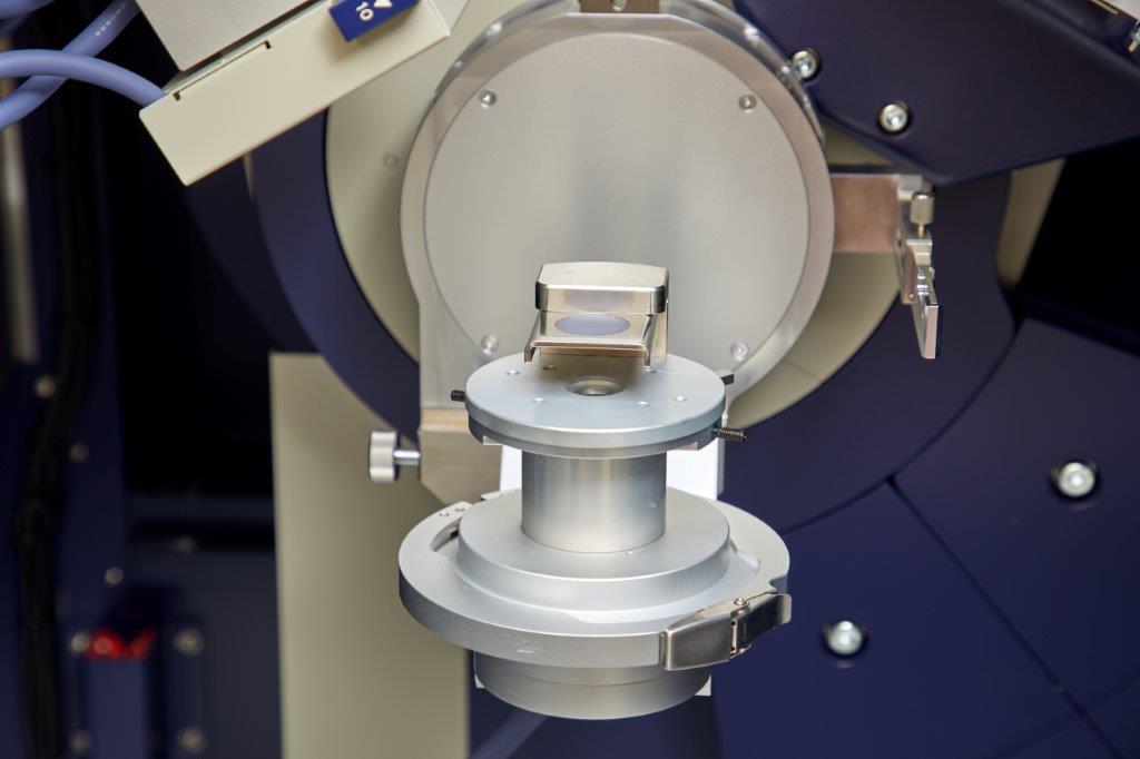
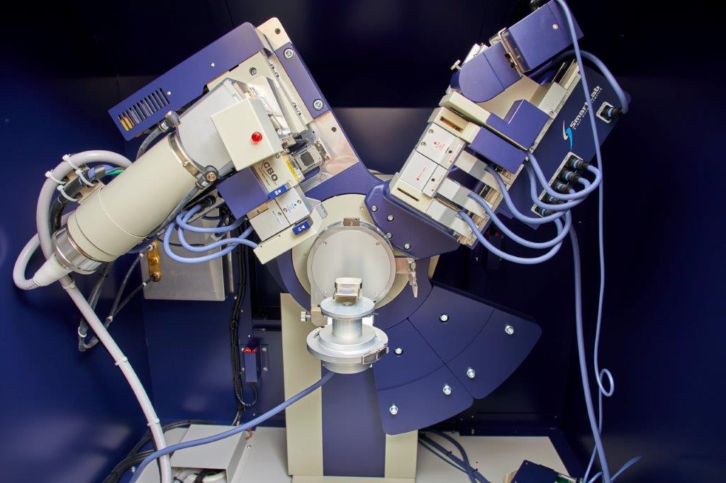
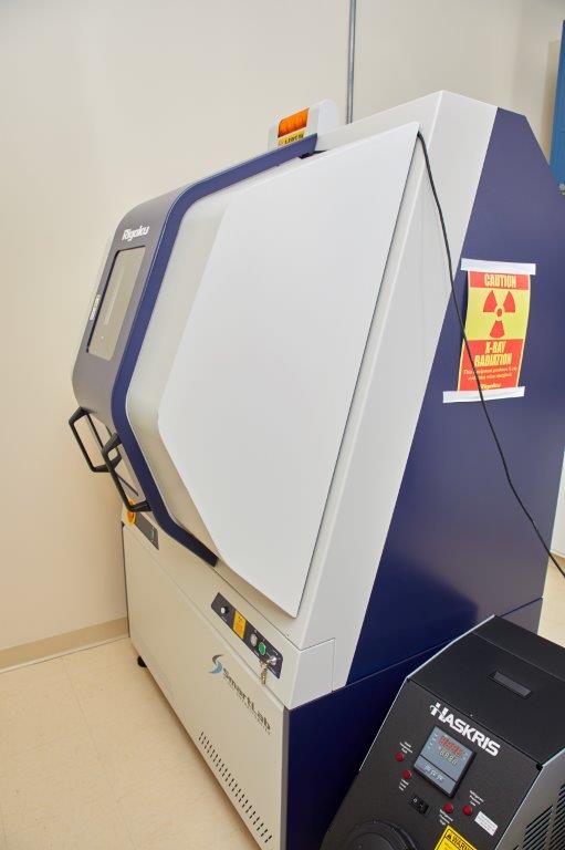
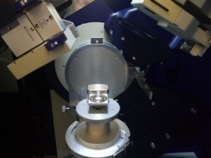
With the addition of our Rigaku SmartLab X-ray Diffractometer, Ebatco can now offer a wide range of non-destructive, x-ray based characterization techniques.  The Rigaku SmartLab X-ray Diffractometer is designed for quickly switching between parallel beam and Bragg-Brentano modes, allowing us to provide everything from high resolution single crystal measurements to powder diffraction services with a minimum of instrumental setup time. Several experimental methods are available, including X-Ray Diffraction, X-Ray Reflectivity, Powder Diffraction, and reflective Small Angle X-ray Scattering.  Identification of unknown phases, determining lattice parameters of crystalline materials, measuring residual stress and strain, and thin film structural characterization are all possible with one machine.

X-rays can be used to study the atomic scale structure of materials using the principles of diffraction. By scattering x-rays from a sample and measuring the intensity as a function of the scattering angle, it is possible to determine the distance between scattering objects. In X-Ray Diffraction (XRD), these are atomic planes in crystals, which can be used to identify the material, determine the atomic structure, or measure strain. In X-Ray Reflectivity (XRR) and small angle x-ray scattering, these distances measure the dimensions of thin films and nanoscale objects.


Phase Identification

A crystal’s diffraction pattern is a unique signature that can be used to identify unknown materials.  Polycrystalline materials or powders are made up of small crystallites in many orientations, making an XRD measurement especially straightforward.  The diffraction pattern of an unknown material can be compared to a database of patterns from known standards – when a match is found, unknown phase can be identified.  The SmartLab’s phase identification capabilities are best suited for polycrystalline materials and powders, which encompass a surprising number of materials such as aluminum foil, concrete, and fridge magnets.


Crystallite Size and Residual Stress

After measuring a material’s x-ray diffraction pattern, it is possible to determine the average size and residual stress of the constituent crystallites. Size and stress affect the width of diffraction peaks, but with different dependencies on the scattering angle.  By measuring the width of many diffraction peaks and fitting the results, the average dimensions and strain can be determined.


Thin Films

X-ray diffraction is not limited to powders or bulk materials – it is one of the best ways to characterize the structure of thin films.  Whether single or poly crystalline, XRD can measure the lattice parameters of thin films and coatings very accurately.  A film’s strain state, degree of relaxation, and orientation with respect to the substrate can be determined.  In some specialized cases, the alloy composition can be found.

We can also test nanoscale thin films using reflectivity. XRR measures the thickness of thin films up to 500 nanometers thick and can provide measurements of surface and interface root mean square (rms) roughness with sub-nanometer resolution.  This technique is admirably suited for films with multiple layers as well, such as heterostructures or superlattices.  XRR is not restricted to crystalline materials and works for amorphous films as well.

Typical Experimental Results

Alumina polishing powder crystallite size and structure

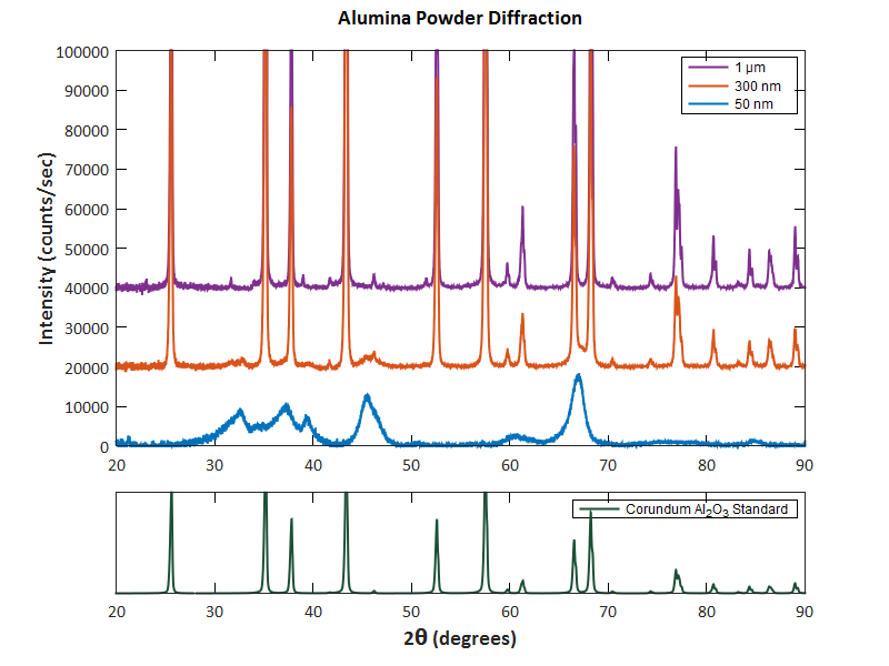
The average size of crystallites in a material (grain size) can be determined from the width of powder diffraction peaks.  We measured the x-ray diffraction pattern of alumina particles used for metallographic polishing.  Using the Halder-Wagner method, we were able to determine the crystallite size and residual strain in three different nominal particle sizes; 1 um, 300 nm, and 50 nm.

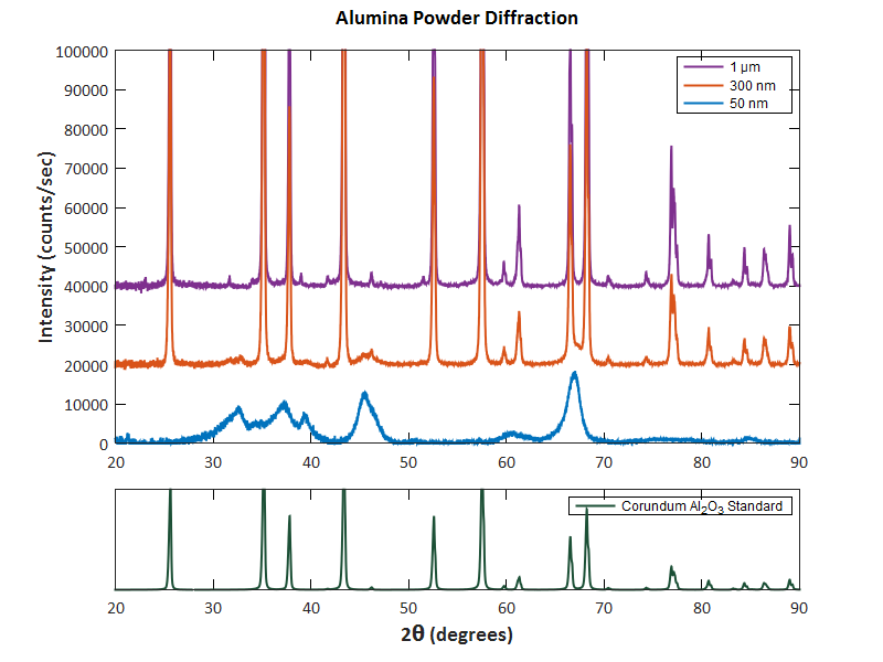
Figure 1. XRD patterns from 1um, 300 nm, and 50 nm alumina particles compared to the corundum phase of Al2O3.


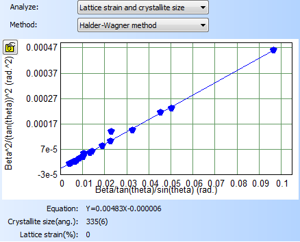
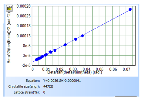
Figure 2. Crystallite size and strain analysis from diffraction peak widths.

Table 1 Average crystallite size and lattice strain of alumina polishing powders calculated from the XRD patterns in Figure 1.

Particle Size Crystallite Size (nm) Strain
50 nm 2.14 ± 1.8 0%
300 nm 33.5 ± 0.6 0%
1 µm 44.7 ± 0.2 0%

Applications


Alloys Ceramics Composition Analysis Concrete
Crystallite Grain Size Epitaxy and Relaxation Film Thickness and Roughness Geological Samples
Heterostructures and Superlattices Lattice Parameters Materials Science Metallurgy
Nanomaterials Phase Identification Polymer Degree of Crystallinity Residual Stress
Semiconductors Structure Determination Structure Mapping (XY Stage) Thin Films

For more information please read our application notes:

Phase Identification and Crystallite Size Measurement using X-ray Diffraction

Mineral Identification in Geological Samples

Nanoscale Film Thickness, Interfacial Roughness, and Density Measured Using X-Ray Reflectivity

Quantitative Composition Determination of Powder Mixtures using XRD

Residual Stress Measurements of a TiN Coating

Instrument: Rigaku SmartLab X-ray Diffractometer

Key Specifications

X-ray Generator Maximum Power 3 kW
Tube Type Cu Long-Fine Focus X-ray Tube
Peak Intensity Wavelength 1.54Å (Cu Kα)
Tube Focus 0.4 x 12mm
Optical Modes Parallel beam, Bragg-Brentano
Monochromator Options Channel cut Ge (220) 2-bounce
Graphite crystal analyzer
Ni foil (filters Cu Kβ)
Goniometer 2θ Range -3° to 160°
Goniometer Resolution 0.0002°
Scanning Speed 0.01°/min – 20°/min
D/teX 250 Silicon Strip Detector Active Area 19.2 x20mm
Pixel Size 75μm
Maximum Sample Dimensions 15 x 15 x 1cm
Sample Holder Types Flat stainless steel (with magnetic holders for wafers <0.3mm thick)
Glass slide with well for powders
Capillary stage for powders
100 x 100mm XY mapping stage


Phase Identification and Crystallite Size Measurement
 Using X-ray Diffraction
 

X-ray diffraction (XRD) is a non-destructive characterization technique which can be used for the identification and structural characterization of single crystal and polycrystalline materials.  A surprisingly large number of materials fall into this category – metals, ceramics, salts, some polymers, semiconductors, and even table sugar.  Unknown compounds can be identified by comparing a sample’s diffraction pattern to a library of patterns measured from over 400,000 materials. The peak positions, widths, shapes, and relative intensities of an x-ray diffraction pattern all give additional information about the solid-state structure and composition. X-ray diffraction is a powerful tool for many industries and applications, such as identifying mineral compositions of geological samples, measuring phase purity for quality control, or distinguishing between phases with identical chemical compositions such as austenite and ferrite in steel.

Figure 1. X-ray diffraction patterns of 1µm, 300 nm, and 50 nm alumina powders (top) and x-ray diffraction pattern of corundum from database of standard diffraction patterns (bottom).

The XRD patterns of alumina polishing powders with nominal particle sizes of 1µm, 300 nm, and 50 nm were measured using Rigaku SmartLab X-Ray Diffractometer.  Figure 1 shows the experimental results from the three samples in comparison with the reference pattern for corundum from a diffraction file database.  It can be seen that the peak positions and intensities of the 1µm and 300 nm particles match those of corundum, the same form of Al2O3 as in ruby and sapphire.  The 50 nm particles have distinctly different diffraction pattern from the 300 nm and 1µm particle samples.  The increased peak width is a result of the reduction in crystallite size. The missing and shifted peaks indicate that the structure has been significantly altered from perfect corundum.  While chemically it may still be alumina, the structure might have more imperfections, damages or plastic deformation.  Plastic deformation in crystals is accommodated by cracks, voids, and strain, all of which produce peak shifts and broadening as seen in the 50 nm sample.

In addition to peak positions and intensities, the width of the diffraction peaks also yields information about the sample’s microstructure.  The crystallite size and microstrain have different dependencies on the x-ray scattering angle.  Figure 2 shows a Halder-Wagner plot used to independently measure the strain and crystallite size of the sample. 

Figure 2. Halder-Wagner plot for the XRD pattern from 1 µm sized alumina particles.

Table 1 shows the results of the size and strain analysis for the three samples.  Grain size plays a role in nearly every important material property, such as hardness, ductility, diffusion rates, resistance to corrosion, electronic conduction, and magnetic properties.  The high density of grain boundaries in the 50 nm particles is likely to make them harder (requires more force to induce plastic deformation) than the particles with larger crystallite size.  Since it takes more energy to move a dislocation across a grain boundary than through the middle of a grain, decreasing the grain size generally increases the hardness of materials. 

Table 1 Average Crystallite Size and Lattice Strain of Polishing Alumina Powders

Particle Size

Crystallite Size (nm)

Strain

  50 nm

2.14 ± 1.8

0%

300 nm

33.5 ± 0.6

0%

    1 µm

44.7 ± 0.2

0%

Quantitative Composition Determination of Powder Mixtures Using XRD

Material composition is an essential piece of information for engineering, quality assurance, trace element analysis, process controls, and research and development.  In ceramics, alloys, steels, geology, and many other fields knowing the composition and crystallographic phase of a material is vital to accurately predicting its performance.  With x-ray diffraction (XRD), it is possible to determine the type of material and weight fraction of multiple components in the same sample. XRD has the advantage of being non-destructive and does not require large sample volumes.  This method works best for any polycrystalline sample with randomly oriented grains that are less than 10 μm in size, which includes many metals, alloys, geological samples, powders, ceramics, and cements.

Figure 1. Powder mixture in low-background sample holder during XRD experiment.

There are three stages to measuring composition with XRD: acquiring the diffraction pattern, identifying the crystallographic phases present in the sample, and refining a model to determine the amount of each phase. Materials are identified by comparing the sample’s diffraction pattern to those in a pattern library containing hundreds of thousands of standards.  Each crystallographic phase has a unique diffraction fingerprint, allowing for the identification of the materials present in the sample.  The final step is fitting the whole powder pattern to a theoretical model.  The total intensity of each phase’s pattern is proportional to the amount present in the sample.  A model of the phases is used to calculate a theoretical diffraction pattern which includes strain, changes in stoichiometry, texture, or sample and instrument misalignments. These variables are refined using the Rietveld method and produce composition measurements good to 5 wt % for many applications.

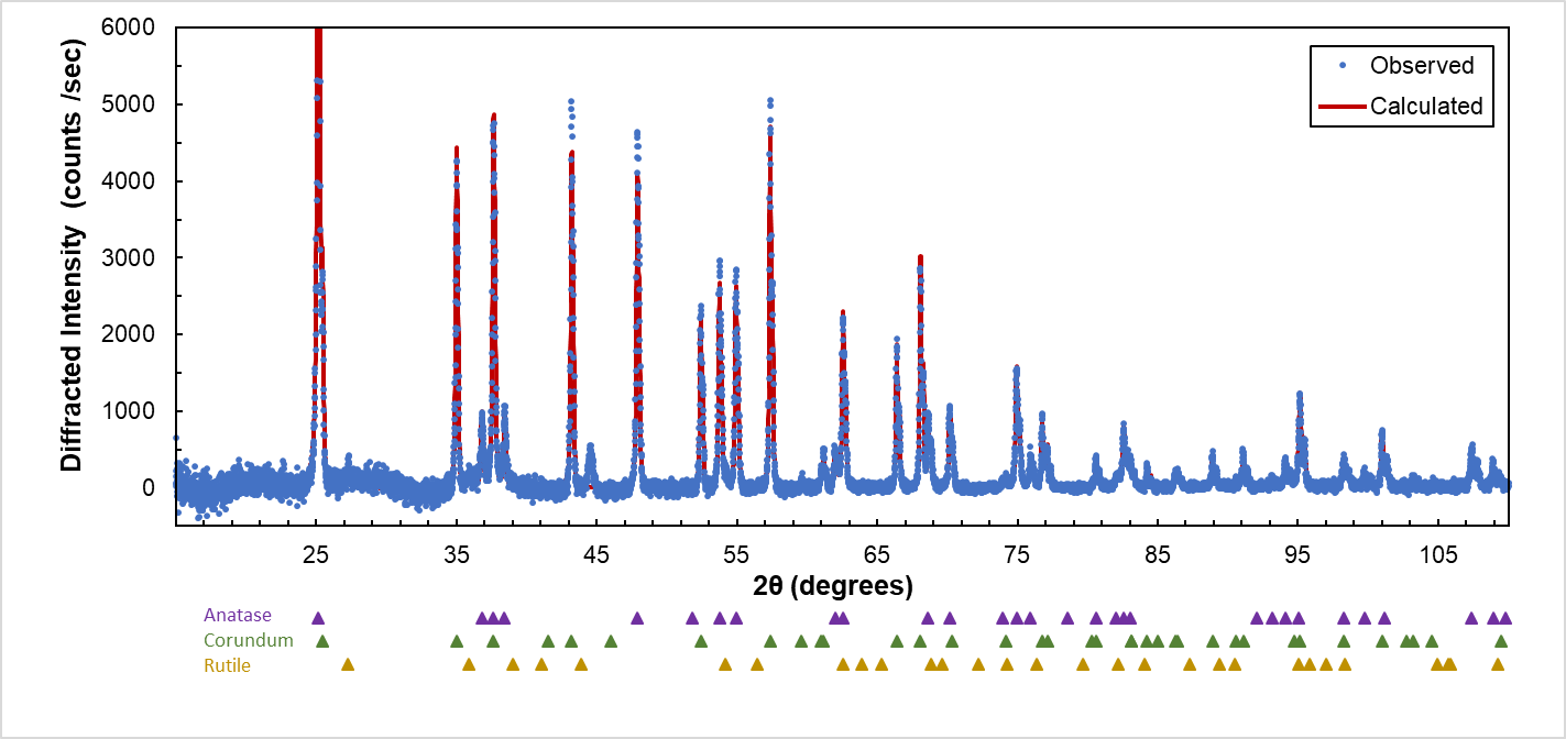
In this demonstrative experiment, a mixture of two known, polycrystalline powders was tested for phase identification and composition measurement using a Rigaku SmartLab X-ray Diffractometer.  The powder mixture was placed in a low-background sample holder and pressed to produce a smooth, flat surface, as shown in Figure 1.  The Cu x-ray source, detector, and sample were all aligned.   A nickel foil was used to selectively absorb the Cu Kβ. The specular powder diffraction pattern was measured with the D/TeX 1D detector at 2°/min over a 2θ range of 15 to 110°.

Figure 2. Experimental and calculated x-ray diffraction pattern from the powder mixture.  The ideal peak positions for anatase, corundum, and rutile are marked with purple, green, and gold triangles, respectively.

The experimental diffraction pattern from the powder mixture is shown above in Figure 2.  The phases were identified as corundum (Al2O3) and anatase (TiO2) with the PDXL 2 analysis program using the Crystallography Open Database powder diffraction library. Rutile (another form of TiO2) may be present at or below 1.1 wt %.  Reference markers below the data indicate the ideal peak positions for each phase. The whole pattern was fit to a model in PDXL 2 in which the Lorentz polarization, the Kα1 and Kα2 splitting, and sample self-absorption were accounted for.  The weight fraction, lattice constants, thermal vibration parameters variables were fit to the experimental pattern for each phase.  The resulting calculation from the best-fit model closely matches the experimental pattern (Rwp = 2.55%) and is shown as the red line in Figure 2.

As an independent check for the XRD results, the elemental composition of the sample was determined using Energy Dispersive X-ray Spectroscopy (EDS).  The weight percent of each phase was calculated assuming ideal stoichiometry.  As EDS does not distinguish between crystallographic phase, the weight percent of TiO2 is a sum of anatase and rutile.  As seen below in Table 1, the composition measurements from XRD and EDS are in agreement.

Table 1 Powder Mixture Composition Results from XRD and EDS

Chemical Formula

Phase

XRD
(wt. %)

EDS
(wt %)

Al2O3

Corundum

59.8 ± 2.2

62.48 ± 3.55

TiO2

Anatase

39.1 ± 2.2

37.52 ± 4.09

Rutile

  1.1 ± 2.1